

Stall and Surge in Gas Turbines
If it sounds as though these two terms in relation to gas turbine engines sounds bad, then you are correct. Stalling in anything aerofoil-shaped in aviation is not good and as modern gas turbine engines use axial flow compressors with aerofoil-shaped blades, it follows that stalling could be disastrous.
The term surge comes from what could happen if a stall is allowed to develop in a compressor. In essence it can reverse the flow!
Why are we bothered apart from the possibility of wrecking our engine? Imagine if you were a paying passenger and had a seat where an engine was within your view and suddenly there was a large BANG and flames came out of the INTAKE. It is possible that the cabin crew might (?) be able to explain flames from the exhaust (even though they didn’t believe it was normal) but they will not be able to calm passengers that a flame from the intake is normal – the result is a cabin full of very excitable passengers (and a very poorly engine).
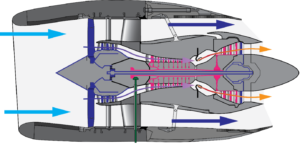
Normal Engine Airflow
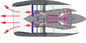
Surge Airflow

Japan Airlines Engine Stall & Surge
(Image By Glenn Beltz from Goleta, CA, USA)
What, then, could the problem be?
As with all aerofoil shapes the airflow over them MUST be smooth or the result is breakaway and turbulence. In a compressor this is then compounded on the next stage and so on through the spool.
The airflow control throughout the axial flow compressor is critical. The possibility of stall, and worse of surge is ever-present. Stall is defined as the partial breakdown of airflow, whereas surge is defined as the complete breakdown of the airflow control.
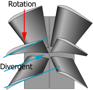
Owing to the construction of this type of compressor we must deal with the angle at which the air impinges on the blades. The first possible problem is guiding the atmospheric air on to the first stage of rotor (or fan) blades. If we get this wrong and the airflow stalls, then turbulent air will render all the subsequent airflow useless for the purposes of compression. It could lead to the destruction of blades owing to the stress put on them. If a blade breaks off the compressor and travels through the remaining stages, the spool will be destroyed. It is therefore necessary to design an engine with several safety devices which prevent this happening. To this end there are 5 generally accepted design features which are incorporated.
Before we look into the design features that are incorporated to prevent stall (and hopefully surge) we must list the things that are most likely to cause the problem.
- Excessive fuel flow on positive and negative acceleration
- Operating engines outside the normal parameters
- Damage or shape change to rotor or stator blades causing turbulent airflow
- Turbulent airflow entering the engine from ambient air.
The features that can prevent the stall are:
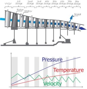
- Variable Inlet Guide Vanes (VIGVs)
- Variable Stator Vanes (VSVs)
- Compressor Bleeds (not to confused with compressor bleed valves)
- Multi Spool Compressors
- Active Clearance Control (ACC)
In one way or another most of these devices will ensure smooth airflow. We live in hope that pilots will operates their aircraft with normal parameters, and that they are aware that blade shape change can be the result of icing or the accumulation of outside contaminants or even birds!
1. Variable Inlet Guide Vanes (VIGVs)


VIGV’s
The idea of this device is that dependant on the RPM of the engine the air entering the intake is “shaped” to impinge on the Fan or 1st stage compressor blades at the appropriate angle to ensure smooth airflow. It is computer controlled.
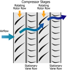
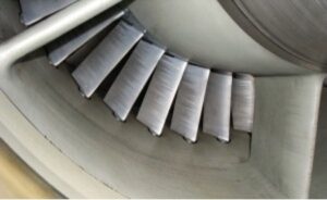
2. Variable Stator Vanes (VSVs)
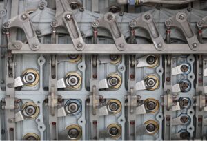
This image shows 5 stages of VSVs are moved via rings
Once over the first rotor blade stage the air now needs to be “shaped” to impinge on the next rotor stage at the appropriate angle. This is done by the VSVs which are computer controlled.
3. Compressor Bleeds
Gas turbine engines are designed to run at high RPM. When run at anything other than this there exists a possibility of pressurised air “build-up” which could cause a blockage to smooth movement of air through the compressor. This could lead to stalling. The ability to “relieve” some pressure helps with the control of this problem. They are generally positioned at the higher compression end of the spool.
4. Multi-spool Compressors
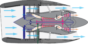
CFM56 Two Spool Engine
As engines became bigger it was noticed that acceleration of one massive compressor meant that acceleration was slow, and that could lead to major problems if the pilot was faced with a situation where power was needed NOW! If the compression side was broken into smaller spools, they could each accelerate/decelerate much more quickly and efficiently.
5. Active Clearance Control (ACC)
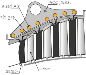
Originally designed for turbine blades to run as close to the casing as possible without any risk of touching. The ability to change the clearance in the air annulus of an axial flow compressor to suits the airflow seems very difficult, and until the problem was addressed at the turbine would have been impossible. However, if a jacket through which hotter or colder air is passed can expand or contract the casing the clearance can be affected. This is, of course, computer controlled.
This blog is designed to address the complexity of compressor control and does not seek to replace an instructor. If it has whetted your appetite for the full explanation then it has achieved its aim!
Still unsure which revision method is right for you? Our instructor-led online revision sessions offer real-time support, 1-1 or group learning, and focused ATPL exam preparation. Visit evoATPL.com